
I live in Topeka KS. I. am pretty handy at this stuff so it shouldn't be a big deal to do it manually. I. just don't want to mess up my extended warranty that I bought my wife would kill me lol. Didn't want to pay 180 anyway but the remote controlled switch was pretty cool. Thanks again for your reply.
You are using an out of date browser. It may not display this or other websites correctly.
You should upgrade or use an alternative browser.
You should upgrade or use an alternative browser.
Need step-by-step instructions on playing DVD in front
- Thread starter marctronixx
- Start date
🤖 AI Summary
No AI summary has been generated for this thread yet.
marctronixx
Staff member
its two wires. Vehicle speed sense wire and parking brake. get a buddy who is good at soldering if you are afraid to. its really a simple mod. i did it on two cars and i am far from a soldering expert like tone is.
maverick415
New member
I did the $60 mod myself but didn't solder, I just used wire crimp connectors. To get to the head unit I didn't have to take out the glove box. Also I just moved the center console cover back a few inches to give me enough clearance. The only parts I removed were the side panels and head unit framing cover.
tonelab77
New member
I didn't take out the glove box either (like some tutorials would have you do). Relieved me to not have to deal with the airbag and resetting it, etc. I'd still remove the center console cover though. I'd never forgive myself if I damaged it...and neither would my wife. As a matter of fact, I did this (under pressure) without her knowledge of what was going on. But it turned out favorably, so I let her in on it after the fact. No harm, no foul. 
______________________________
tonelab77
New member
I'm going to try to be very detailed in these instructions, but please let me know if something doesn't make sense, and I'll try to explain it further.
First of all, you should read this thread in its entirety (if you haven't done so already). Then follow instructions below.
These are the best instructions for taking the interior apart: https://docs.google.com/file/d/1AhhyMi3x2TmHMnFbFvHg5y3EptedIgVcsboonj4KU6z-pOgKrc6EO1Efw9T-/edit?usp=sharing
Here is the Audio Video Service Manual for the QX56. Page 51 shows the terminal layout: https://docs.google.com/file/d/0B9Svsct5noIfUzVBejREOHZJTlk/edit?usp=sharing
You can try your luck with a screw driver wrapped in cloth of some sort. Or, you can spend $5 for these interior disassembling pry tools for the center console: http://www.harborfreight.com/4-piece-nylon-pry-bar-installer-kit-69668.html
I soldered everything together to make secure connections. If you don't know how to solder, don't worry. It's not that hard. Get the cheapest soldering iron, solder, and flux from Rat Shack, watch a couple of youtube videos and practice on stuff you don't mind messing up on first. After 15-30 minutes of practice, you should be a pro") . If you're still not comfortable soldering, find someone who is and have them do it for you.
. If you're still not comfortable soldering, find someone who is and have them do it for you.
Buy a DPDT switch for $4 from Rat Shack like this one: http://www.radioshack.com/product/index.jsp?productId=2062525
Get a decent pair of small wire strippers.
Get two feet of CAT5 or CAT6 (solid not stranded) Ethernet cable and take the sleeve off. You should now have 4 twisted pairs (blue/green/brown/orange). You can discard one pair (I discarded the blue). I used the green pair for ground, the brown pair for the wires going to the AV Control Unit, and the orange pair for the wires going away from the AV Control Unit. Strip an 1/8th of an inch from all wires to be used. With the solid strand of all twelve wire ends exposed, add a tiny bit of flux to each wire, then "tin" each one, and while you're at it, tin all six connectors on the DPDT rocker switch too. Tinning means getting solder onto the wires or connectors...kind of like prepping what you're working on. It makes it a lot easier to make connections whilst working in your expensive luxury SUV.
Once you have the AV Control Unit wires cut, tin them too.
The following numbers represent the back connectors of the DPDT switch. Wire it up like this:
1 4 (1 = Brown ethernet wire, 4 = Brown/White ethernet wire)
2 5 (2 = Orange ethernet wire, 5 = Orange/White ethernet wire)
3 6 (3 = Green ethernet wire, 6 = Green/White ethernet wire)
Solder these to the corresponding AV Control Unit wires below before you wire them to the DPDT rocker switch.
#1 is VSS away from AV (Brown/White wire at pin 82 on the 32 pin connector)
#4 is Parking Brake away from AV (White wire at pin 65 on the 32 pin connector)
#2 is VSS TO AV (Brown/White wire at pin 82 on the 32 pin connector)
#5 is Parking Brake TO AV (White wire at pin 65 on the 32 pin connector)
#3 & #6 Go to GROUND (which can and should be the same ground)
Note: I used the upper left screw (there are four) that holds in the AV Control Unit for grounding both Green and Green/White ethernet wires. I also soldered these two wires together. The exposed portion of them can be an inch long so you wrap them around the grounding screw securely.
The following picture is from a member of another Nissan/Infiniti forum regarding the same mod (ignore the colors written on the sketch):

First of all, you should read this thread in its entirety (if you haven't done so already). Then follow instructions below.
These are the best instructions for taking the interior apart: https://docs.google.com/file/d/1AhhyMi3x2TmHMnFbFvHg5y3EptedIgVcsboonj4KU6z-pOgKrc6EO1Efw9T-/edit?usp=sharing
Here is the Audio Video Service Manual for the QX56. Page 51 shows the terminal layout: https://docs.google.com/file/d/0B9Svsct5noIfUzVBejREOHZJTlk/edit?usp=sharing
You can try your luck with a screw driver wrapped in cloth of some sort. Or, you can spend $5 for these interior disassembling pry tools for the center console: http://www.harborfreight.com/4-piece-nylon-pry-bar-installer-kit-69668.html
I soldered everything together to make secure connections. If you don't know how to solder, don't worry. It's not that hard. Get the cheapest soldering iron, solder, and flux from Rat Shack, watch a couple of youtube videos and practice on stuff you don't mind messing up on first. After 15-30 minutes of practice, you should be a pro
. If you're still not comfortable soldering, find someone who is and have them do it for you.Buy a DPDT switch for $4 from Rat Shack like this one: http://www.radioshack.com/product/index.jsp?productId=2062525
Get a decent pair of small wire strippers.
Get two feet of CAT5 or CAT6 (solid not stranded) Ethernet cable and take the sleeve off. You should now have 4 twisted pairs (blue/green/brown/orange). You can discard one pair (I discarded the blue). I used the green pair for ground, the brown pair for the wires going to the AV Control Unit, and the orange pair for the wires going away from the AV Control Unit. Strip an 1/8th of an inch from all wires to be used. With the solid strand of all twelve wire ends exposed, add a tiny bit of flux to each wire, then "tin" each one, and while you're at it, tin all six connectors on the DPDT rocker switch too. Tinning means getting solder onto the wires or connectors...kind of like prepping what you're working on. It makes it a lot easier to make connections whilst working in your expensive luxury SUV.
Once you have the AV Control Unit wires cut, tin them too.
The following numbers represent the back connectors of the DPDT switch. Wire it up like this:
1 4 (1 = Brown ethernet wire, 4 = Brown/White ethernet wire)
2 5 (2 = Orange ethernet wire, 5 = Orange/White ethernet wire)
3 6 (3 = Green ethernet wire, 6 = Green/White ethernet wire)
Solder these to the corresponding AV Control Unit wires below before you wire them to the DPDT rocker switch.
#1 is VSS away from AV (Brown/White wire at pin 82 on the 32 pin connector)
#4 is Parking Brake away from AV (White wire at pin 65 on the 32 pin connector)
#2 is VSS TO AV (Brown/White wire at pin 82 on the 32 pin connector)
#5 is Parking Brake TO AV (White wire at pin 65 on the 32 pin connector)
#3 & #6 Go to GROUND (which can and should be the same ground)
Note: I used the upper left screw (there are four) that holds in the AV Control Unit for grounding both Green and Green/White ethernet wires. I also soldered these two wires together. The exposed portion of them can be an inch long so you wrap them around the grounding screw securely.
The following picture is from a member of another Nissan/Infiniti forum regarding the same mod (ignore the colors written on the sketch):
tonelab77
New member
Anyone please correct me if I'm wrong, but it's the same except that you need to substitute wire 65 for wire 80.
______________________________
marctronixx
Staff member
http://www.clubarmada.com/forums/showpost.php?p=107767&postcount=164
this shows how to do it for an armada. different steps in taking the panels off and also the VSS and park brake are different on the armada.
that site is also the best site for anything armada.
this shows how to do it for an armada. different steps in taking the panels off and also the VSS and park brake are different on the armada.
that site is also the best site for anything armada.
GNOLAUM
New member
I'm going to try to be very detailed in these instructions, but please let me know if something doesn't make sense, and I'll try to explain it further.
First of all, you should read this thread in its entirety (if you haven't done so already). Then follow instructions below.
These are the best instructions for taking the interior apart: https://docs.google.com/file/d/1AhhyMi3x2TmHMnFbFvHg5y3EptedIgVcsboonj4KU6z-pOgKrc6EO1Efw9T-/edit?usp=sharing
Here is the Audio Video Service Manual for the QX56. Page 51 shows the terminal layout: https://docs.google.com/file/d/0B9Svsct5noIfUzVBejREOHZJTlk/edit?usp=sharing
You can try your luck with a screw driver wrapped in cloth of some sort. Or, you can spend $5 for these interior disassembling pry tools for the center console: http://www.harborfreight.com/4-piece-nylon-pry-bar-installer-kit-69668.html
I soldered everything together to make secure connections. If you don't know how to solder, don't worry. It's not that hard. Get the cheapest soldering iron, solder, and flux from Rat Shack, watch a couple of youtube videos and practice on stuff you don't mind messing up on first. After 15-30 minutes of practice, you should be a pro
Buy a DPDT switch for $4 from Rat Shack like this one: http://www.radioshack.com/product/index.jsp?productId=2062525
Get a decent pair of small wire strippers.
Get two feet of CAT5 or CAT6 (solid not stranded) Ethernet cable and take the sleeve off. You should now have 4 twisted pairs (blue/green/brown/orange). You can discard one pair (I discarded the blue). I used the green pair for ground, the brown pair for the wires going to the AV Control Unit, and the orange pair for the wires going away from the AV Control Unit. Strip an 1/8th of an inch from all wires to be used. With the solid strand of all twelve wire ends exposed, add a tiny bit of flux to each wire, then "tin" each one, and while you're at it, tin all six connectors on the DPDT rocker switch too. Tinning means getting solder onto the wires or connectors...kind of like prepping what you're working on. It makes it a lot easier to make connections whilst working in your expensive luxury SUV.
Once you have the AV Control Unit wires cut, tin them too.
The following numbers represent the back connectors of the DPDT switch. Wire it up like this:
1 4 (1 = Brown ethernet wire, 4 = Brown/White ethernet wire)
2 5 (2 = Orange ethernet wire, 5 = Orange/White ethernet wire)
3 6 (3 = Green ethernet wire, 6 = Green/White ethernet wire)
Solder these to the corresponding AV Control Unit wires below before you wire them to the DPDT rocker switch.
#1 is VSS away from AV (Brown/White wire at pin 82 on the 32 pin connector)
#4 is Parking Brake away from AV (White wire at pin 65 on the 32 pin connector)
#2 is VSS TO AV (Brown/White wire at pin 82 on the 32 pin connector)
#5 is Parking Brake TO AV (White wire at pin 65 on the 32 pin connector)
#3 & #6 Go to GROUND (which can and should be the same ground)
Note: I used the upper left screw (there are four) that holds in the AV Control Unit for grounding both Green and Green/White ethernet wires. I also soldered these two wires together. The exposed portion of them can be an inch long so you wrap them around the grounding screw securely.
The following picture is from a member of another Nissan/Infiniti forum regarding the same mod (ignore the colors written on the sketch):
Hey I live in San Diego. If you can figure this out for an '06 I would probably make the journey for you to help me....
I would buy you beer, but wouldn't share with you cuz I don't drink.
tonelab77
New member
For your year I believe you need something called nav 2 go. I have experience with it either. Maybe someone else can chime in.
______________________________
marctronixx
Staff member
yeah cars prior to the HDD system have a different wiring scheme...
Did the car kit mod to day. Worried more about tearing apart the dash than the time to do it.
Went very well, the direction and pics were spot on. Took me about 25-30 minutes. The only thing I would recommend is to put the shift lever into D. It makes getting the console over the lever easier. I didn't unplug the 3 cables from the console, just rotated it out of the way. The supplied remote works as it should as do all of the regular functions.
Let me know if anyone has questions on this mod.
tonelab77
New member
I believe it is on-off. lol
______________________________
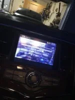
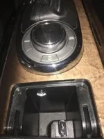
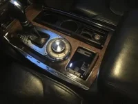
This really helped me! I just completed this last weekend. I will post some pics of the final results (Sorry, did not think to take pictures as I was doing it).
As promise here are some pictures. I put the button inside the USB housing because the light was a little bright and it would have been a little distracting. I actually like it there better then where I originally plan it. Follow the instructions and made my own kit, not to hard.
As promise here are some pictures. I put the button inside the USB housing because the light was a little bright and it would have been a little distracting. I actually like it there better then where I originally plan it. Follow the instructions and made my own kit, not to hard.
Attachments
tonelab77
New member
Awesome man! I'm glad it helped! We sold our beautiful 2011 QX 3 days ago and I've been missing her, but not her MPGThis really helped me! I just completed this last weekend.
") . Now I just found out that to do this on a Mercedes, I'll have to buy some BS software (video in motion...or some BS). Not happy about that
. Now I just found out that to do this on a Mercedes, I'll have to buy some BS software (video in motion...or some BS). Not happy about that 
 | ||||
| | | | | |
| | | |||